Thread Charts
Screw Threads
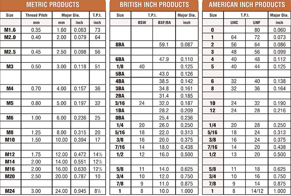
Threaded fasteners thread detail with eight charts and video showing thread production with a link to a history of threads.
click on the images
UNC-UNF SUPPLIERS BSW-BSF SUPPLIERS
HISTORY OF THREADS THREAD ROLLING VIDEO
quick view
The Thread Rolling Process
Cold Forming of threads is displacing and does not waste material
A cylindrical blank having an outside diameter between the major and minor diameters of the finished thread is rotated between hardened steel dies bearing the reverse thread form.
The die threads penetrate the blank surface to form the thread roots and displace material radially outward to form the crests. Metal is neither removed nor wasted but displaced.
Improved Tensile Strength, Shear & Fatigue Resistance
The Thread grain structure is not severed; instead, it is re-formed in continuous unbroken lines following the thread contours. Rolled threads have increased resistance to stripping because such failures are compelled to take place across, rather than with, the grain flow.
Threads are produced with burnished roots and flanks, free from surface imperfections that might prove to be starting points for fatigue failure. Surface layers of the thread, particularly those in the roots are stressed in compression. These compressive stresses must be overcome before the tensile stresses that cause fatigue failure can be built up.
VERY SHORT TWO DIE THREAD ROLLING VIDEO
VERY SHORT FLAT-DIE THREAD ROLLING VIDEO
HISTORY OF THREADS
Besson in France contrived a screw-cutting gauge to be used on lathes in 1569. In 1641, screw cutting was further improved by Hindley of York, England. In 1760 Job and William Wyatt took screw cutting a stage further. Henry Crum Patent the same Wyatt machine in the USA 76 years later in 1836. Henry Maudslay's career began in 1789 as a blacksmith, making machinery for Joseph Bramah the famous locksmith. When Henry Maudslay later went on to establish his own company, his work was influenced by precision. In the early eighteenth century machines were primitive, there were no standard measures, parts would have to be individually engineered, nuts and bolts would be made to fit as a pair and were not interchangeable. Henry Maudslay was among one of the first to recognise the importance of standardisation and interchangeability of machine parts, his major engineering contribution was his large screw-cutting lathe. Henry Maudslay's lathe was far superior to any of its predecessors and as such, it became widely used. It is not surprising therefore that Joseph Whitworth chose Maudslay's works as the starting place for what was to become his very successful career.
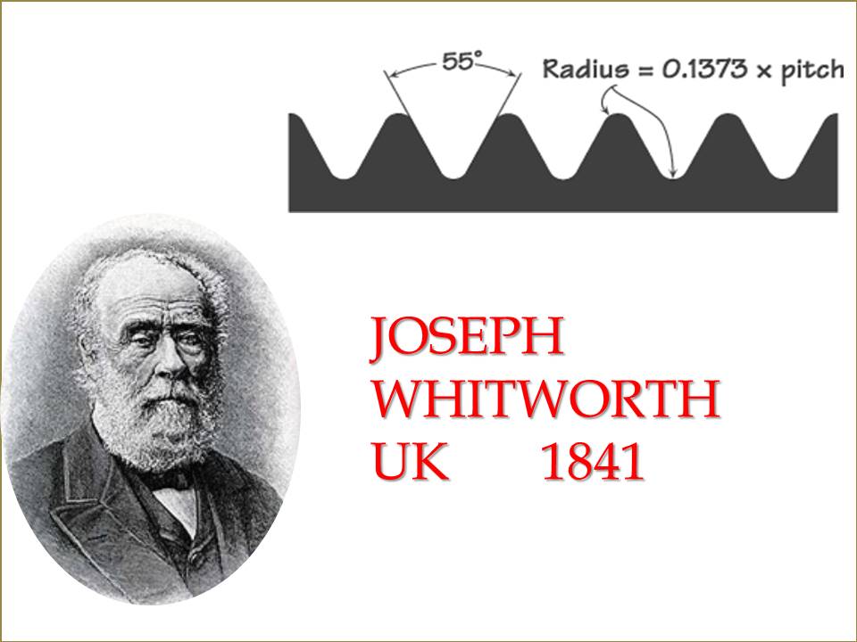
Joseph Whitworth
Maudslay took on Joseph Whitworth as an apprentice, who proved exceptionally talented. He next worked at Joseph Clements, where they were trying to build Babbage's calculating engine, the first computer, and finally set up shop for himself as a toolmaker.
Whitworth set himself the task of devising a standard for threads. He also collected bolts from all over England, noting which sizes had shown to be most useful, and the results of various thread forms. In 1841 he proposed as a standard a thread form with an included angle of 55°, and the tops and bottoms of the threads rounded with a radius equal to 0.1373 times the pitch.
Due in part to the immense prestige, Whitworth gained from the display of his machines at the Crystal Palace Exhibition of 1851, Whitworth's system was in general use in Great Britain by 1860. Later a second series with finer threads (BSF British Standard Fine) was added.
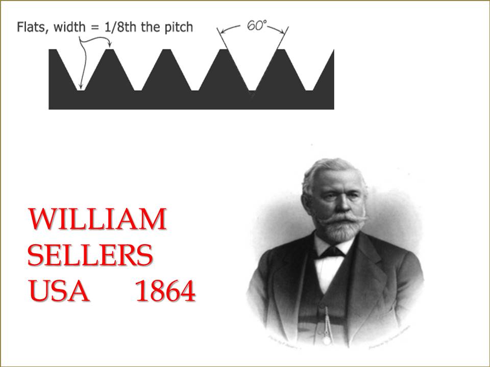
William Sellers
Americans experienced the same problems from the lack of thread standardisation that Britain did. The challenge was taken up by William Sellers, of an eminent family of American technicians. In 1864, a committee of the Franklin Institute recommended the adoption of Seller’s system of screw threads. The thread form became known as the “Franklin thread,” or, more commonly “Seller's thread,” later as the “United States Standard Thread.” and Unified thread.
The main difference between Seller's thread form and Whitworth's is that the tops and bottoms of the threads (the crests and roots) are flattened. The flattened root was a bad choice. Such angular configurations in metal concentrate stress and the process of manufacture result in high stresses at the roots of threads anyway. The result is cracks and broken fasteners. This problem was not so noticeable in Seller’s day thread roots tend to be rounded anyway as the tools that make the bolts become worn. Round roots are now the norm in the USA and the thread is described are UNRC, UNRF the “R” for round root.
The Germans, Swiss and French each developed their own metric screw thread forms. The metric world eventually agreed but not formalised in 1898 on the Systeme Internationale (SI) metric thread series, with a 60-degree thread angle.

